
Introduction
Select Monitor Adapter
Subaru Diagnostic Ports
How to build a PC adapter
Protocol
Software
Troubleshooting
Eavesdropping
Engine Control Unit (ECU)
Description
Reading Error Codes
Reverse Engineering
Modifying
ROM images
Transmission Control Unit (TCU)
Description
Reading Error Codes
Reverse Engineering
Power Mode
Modifying
ROM images
Other Control Units
Air Conditioning Unit 4WS Control Unit Cruise Control Unit
OBD2 Information
Select Monitor Cartridge
Downloads
Links to other sites
Custom TCU Development

Cruise Control Unit

Despite many attempts, I have not been successful in communicating with the SVX Cruise Control Unit.
The developers of FreeSSM discovered an older SSM protocol used by the Subaru L-series. They suggested to me that perhaps the cruise control unit uses this older protocol. It requires clocked synchronous communications and is therefore not compatible with our current design of RS232 to TTL interface.
From looking at the select monitor rom dump, I think that this is correct. The select monitor program appears to configure the serial interface for clocked synchronous communication at 250 baud. The extra wire on pin 4 of the diagnostic connector is presumably to carry the clock signal from the SSM to the CCU.
UPDATE! Noriyasu Mori has successfully managed to communicate with the SVX Cruise Control Unit. He has confirmed that it uses the older SSM0 protocol and has kindly allowed me to publish the details below.
1) baudrate
I'm using the FT232R with bitbang mode, so I can't control the baud rate
precisely, but it seems to work around 250bps. It doesn't work the
baudrate is too slow or too fast.

        11111111111111111111111111111111100001111010010000110110000000000011000110

2) start bit
 It seems that  many preamble "1"s and one start bit "0" is not needed.
 SCI of HD6305 MPU is simple 8bit serial to parallel converter and not
recognize start bit. Once I add the preamble and start bit, the unit
not make a responce.

3) clock timing.
   Data will be latched when clock becomes high level according to
datasheet of MPU. So, I need to give TX data bit with "0" level clock,
then, give "1" level to the clock pin.

3) TX data format
 Data format of read sesuence is as Follows. (LSB first)
Tx Byte1 = command (AB is Cruise Control Unit)
Tx Byte2 = address high
Tx Byte3 = address low
Tx Byte4 = Tx data (Always 00)
Tx Byte5 = checksum

The check sum will be calcualted as follows.
checksum = (0xff - command(0xAB) - addresshigh - address low - Txdata) &
0xff

4) RX data format
 Data format of read sesuence is as Follows.
Preample some bit of "1".
 Note: number of "1" is not fixed and it's may not a multiple of 8.
Rx Byte1 = address high
Rx Byte2 = address low
Rx Byte3 = Rxdata
Rx Byte4 = checksum
Rx Byte5 = 0xff
Rx Byte6 = address high
Rx Byte7 = address low
Rx Byte8 = Rxdata
Rx Byte9 = checksum
Rx Byte10 = 0xff
then repeat ...

The check sum will be calcualted as follows.
checksum = (0xff - command(0xAB) - addresshigh - address low - Rxdata) &
0xff

Note1: Command bytes are not included in the response, but are
calculated in the checksum
Note2: Sometimes response repeat many time, but sometimes not. I have
not find the resaon of it.
Note3: I sometimesl get response, but sometimes not. It seems that it
will be successed at first time from power on. I may need to add STOP
command after I read the responce. I will make more investigate.

5) Data Address

Address will be from 0x0040 - 0x00FF according to memory map of MPU.

I analized Select Monitor ROM data which you provided.
The parameter of this are as follows. Also, I investigated about
relationship between DIO and switchs.

 00a6 (F02) vehicle speed, x1,  Km/h
 009c (F03) engine , x25, rpm
 007a (FA0) DIO
        Bit1 Diagnosis (connect 8pin of B83 Connector to ground)
        Bit2 Sometimims toggled (Unknown)
        Bit3/Bit6 BRAKE/STOP
        Bit4 RESUME Button
        Bit5 SET Button
               Note: Bit4 + Bit5 CANSEL Button
        Bit7 Always toggled (Unknown)
 009d (FB0) CANSEL Fixed value (Unknown)

I had a misunderstanding about TR2 of cruise control unit. It seems
related to self diagnosis function and not select monitor signal.
If you are using 87022PA020 (export version), self diagnosis function
will not work. it seems only for 87022PA000 (Japan domestic version).

6) Stop Command

In SSM0 protcol, it seems that cuirse control unit stop to send responce
once the select monitor stop the clock for a while. 100milisecond seems
enough to do it.

I changed the procidure to control FT232R Bit Bang mode as follows.
It looks work very well.

1) Send serialized command with checksum adding enough extra dummy "1"
bit after that. (Also, toggling the clock pin).

2) Set the data and clock pin level to "1" with sending TX data.

3) Recieve the srialized responce data from buffer of FT232R driver.

4) find the data with desrializing in every 1 bit.
   (compare address and check the checksum)

5) flush all responces data even I found the recieved data. Rx bytes
should be same as sent  bytes of serialied data for FT232R.

6) wait 100ms before send next command.
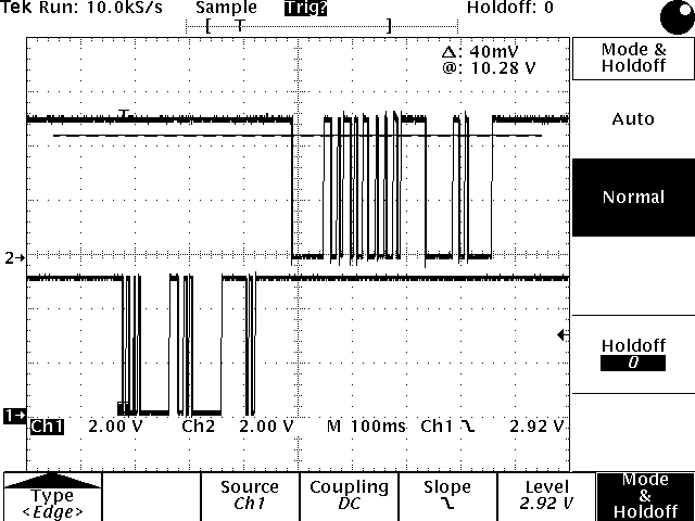
Oscilloscope trace
hd6305 SCI_timing diagam
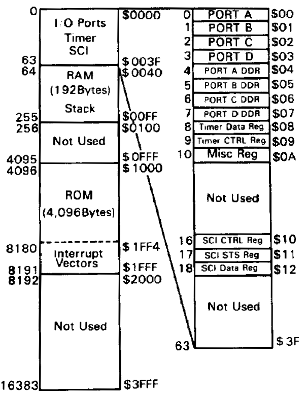
HD6305 Memory Map
HD6305 Memory Map
FT232R_CABLE_R1.2.pdf