
Introduction
Select Monitor Adapter
Subaru Diagnostic Ports
How to build a PC adapter
Protocol
Software
Troubleshooting
Eavesdropping
Engine Control Unit (ECU)
Description
Reading Error Codes
Reverse Engineering
Modifying
ROM images
Transmission Control Unit (TCU)
Description
Reading Error Codes
Reverse Engineering
Power Mode
Modifying
ROM images
Other Control Units
Air Conditioning Unit 4WS Control Unit Cruise Control Unit
OBD2 Information
Select Monitor Cartridge
Downloads
Links to other sites
Custom TCU Development

Subaru Select Monitor Eavesdrop Cable
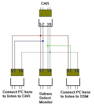
This cable will allow a Select Monitor and a PC to be connected to the car at the same time. The PC will be able to eavesdrop on the conversation between the car and the Select Monitor. This makes it possible to compile a definitive list of the ECU parameters that can be used in VWRX, Evoscan and any other data logging software.
To build the cable, you need 1 male connector (1st Gen Legacy Radio Harness) and 3 female connectors (B35 yellow select monitor connectors).
At one end of the cable is the male Legacy radio harness connector. This connects to the female Select Monitor connector on the car. At the other end of the cable are three female Select Monitor Connectors.
The centre connector is where you plug in the SSM. It's cables go straight through the to male plug. 2-2, 3-3, 5-5 and 9-9. In the description below, "wire 2" and "wire 3" refer to the wires on pins 2 and 3 of this connector.
The left connector is also wired straight through, but pin 3 (transmit) is not connected because this connector only receives data from the car, it does not transmit. You will notice that pin 2 (receive) is connected to wire 2 (transmit from Car to SSM). Data travelling along wire 2 from the Car to the SSM will be received by a PC attached to this connector.
The right connector also has no transmit wire. In addition, its pin 2 (receive) is connected to wire 3 (transmit from SSM to Car). Data travelling along wire 3 from the SSM to the Car will be received by a PC attached to this connector.
You do not need to have two PCs to perform the monitoring, you can have just one PC and move it between the left and right connectors.
How to use get the parameter addresses
- Connect the male connector of the cable to the car.
- Connect the SSM to the centre connector of the cable.
- Connect the PC to the right connector of the cable.
- Run the Hex Com Tool software on the PC and set the parameters to 1953-8-E-1 as normal.
- Switch on the car ignition.
- Switch on the select monitor and read a parameter.
- The Hex Com Tool should show the data sent by the SSM. It should look like 78aaaabb where aaaa is the address that is being queried.
- If the data doesn't look right then possibly the select monitor is using the ASCII mode, in which case, change the HCT parameters to 4808-8-N-1 and try again. In ASCII mode the queries should look like 7Faaaaaaaabbbb and the replies like aaaaaaaannnn0A0D.
- Compile a list of the data sent by the Select Monitor for each parameter that it queries. ECU, TCU, Reset, Cruise, Aircon, whatever parameters you can get. The more info the better.
How to find the conversion formulas
A. Scalar quantities
- The relationship between the data sent by the ECU and the value displayed on the SSM screen is most likely linear. This means that the formula is always y=mx+c, where y is the value displayed on the SSM, x is the value sent by the ECU, m and c are what we have to work out for each parameter.
- Move the PC cable to the left connector so that the PC receives the replies from the Car to the SSM.
- You need to take two different readings of the same parameter. It is best to do this with the engine running. For example, read the MAF at low RPM and again at high RPM. Write down the values sent by the ECU and the corresponding value displayed on the SSM screen. Call the ECU values E1 and E2 and the SSM values S1 and S2
- Use a calculator to convert the ECU values E1 and E2 from hexadecimal to decimal
- Work out m = (S2 - S1)/(E2 - E1)
- Work out c = S1 - (E1 x m)
- Double check that S2=(m x E2) + c
- If m or c are long decimal numbers, try to represent them as fractions. For example 0.0196078 can be represented as 5/255.
B. On-Off Switches
- The values of on/off switches are transmitted as binary bits.
- Read the ECU value when the switch is on, read it again when the switch is off.
- Convert the values E1 and E2 from hexadecimal to binary and compare them. For example, if E1 is 35 hex and E2 is 31 hex. In binary they are 00110101 and 00110001. You can see that the 6th bit is the one that represents the switch you flipped.