Introduction
Select Monitor Adapter
Subaru Diagnostic Ports
How to build a PC adapter
Protocol
Software
Troubleshooting
Eavesdropping
Engine Control Unit (ECU)
Description
Reading Error Codes
Reverse Engineering
Modifying
ROM images
Transmission Control Unit (TCU)
Description
Reading Error Codes
Reverse Engineering
Power Mode
Modifying
ROM images
Other Control Units
Air Conditioning Unit 4WS Control Unit Cruise Control Unit
OBD2 Information
Select Monitor Cartridge
Downloads
Links to other sites
Custom TCU Development

Modifying the ECU
The ECU has provision for an external EPROM, to allow the firmware to be updated. In 1992, Subaru did issue a firmware update for the USDM model SVX but it is unclear what issues this fixed. To update the firmware, you insert an EPROM into the upgrade socket and then cut resistor J1. Cutting the resistor tells the ECU to use the update EPROM rather than the original ROM.
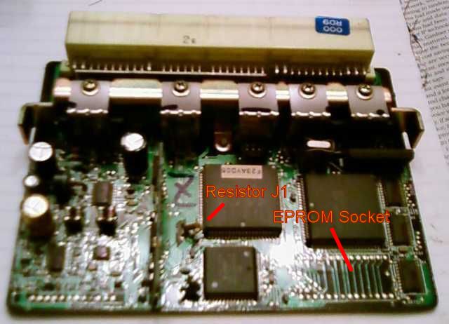
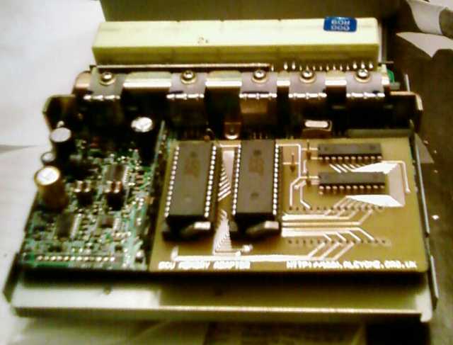
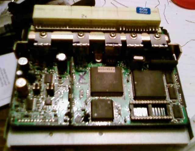
The first obstacle for me was that the JDM version of the ECU doesn't have the EPROM socket fitted. There are just two rows of solder dots on the board. Fortunately, all the circuitry is in place, so it's just a matter of cleaning out the holes and soldering a socket in place. While doing this, I took the opportunity to neatly desolder resistor J1 rather than cutting it.
The next obstacle is the type of EPROM required for the ECU. It is a Fujitsu 27C1028 chip. There are now obsolete and therefore expensive and hard to obtain. There are a few stocks floating around in the tuner community and they appear on ebay occasionally. But even if you find one, you can't program it with any affordable EPROM programmer. It's an unusual chip because it multiplexes the address and data lines over the same set of pins. Only the expensive top-end programmers can support it.
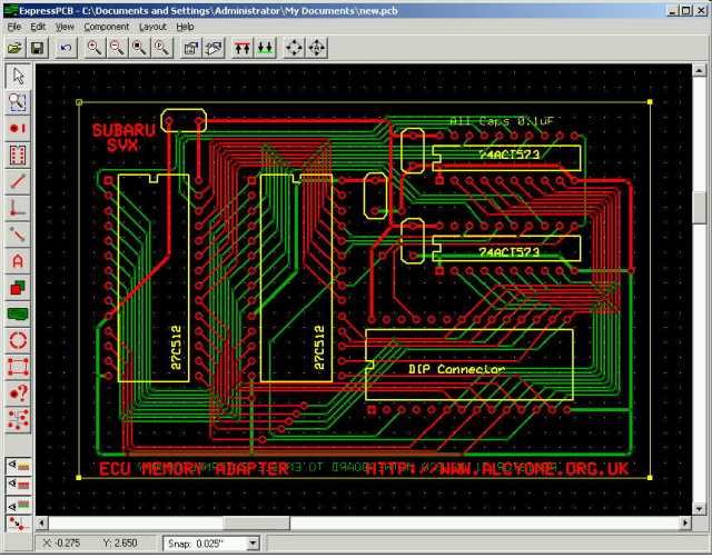
The solution is to build a memory adapter that will allow the use of cheap modern EPROMs in place of the 27C1028. I have built some boards based on the original design by Hitoshi Kashima, with some improvements suggested by Calum Johnson. These boards allow the use of two 27SF512 EEPROMs in place of the 27C1028 EPROM. It is cheap and easy to build these boards for yourself. Follow the steps below.
Step 1 - Ordering the printed circuit boards.
Go to http://www.expresspcb.com and download their printed circuit board design software. Then download my circuit design from here. Run the software, load my circuit design, and click on the order option from the menu. Fill in your credit card details and expresspcb will manufacture 3 top-quality boards for you for only US$51 + shipping.
Step 2 - Ordering the components.
The next step is to find a good electronics supplier and buy the the components needed to populate the board. The table below shows the parts necessary for one board. If you are going to build all three then you will need to multiply the quantities by 3.
| Part | Quantity | Link |
| 74HC573 Octal D-Type Latch | 2 | Digikey |
| 0.1uF Capacitor | 4 | |
| 28 pin ZIF Socket | 2 | Aries |
| 27SF512 EPROM | 2 | Moates |
| SamTec BBS-114-T-A 14 Pin Header | 2 | Digikey |
Step 3 - Build the boards.
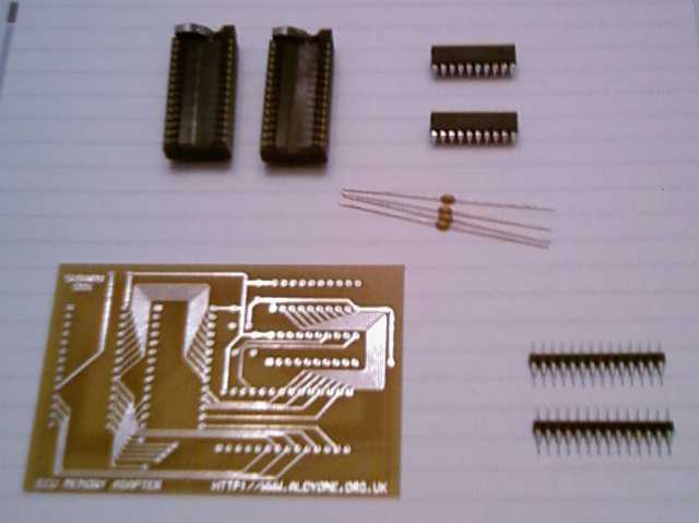
Here is the unassembled board with the components laid out ready.
Fit the latches, ZIF sockets and capacitors to the top side. Refer to the layout and ensure that all the components are pointing in the right direction.
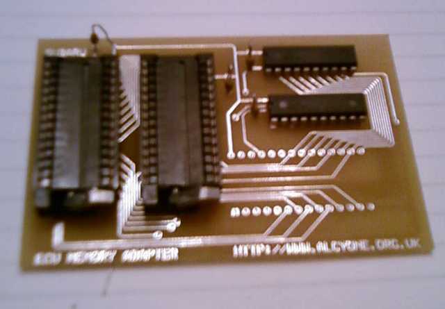
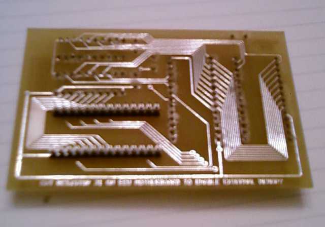
Fit the pin header to the bottom side. The easiest way is to install the pin header in the ECU, then put the board on top and solder the pins. That ensures that everything lines up as it should.
Step 4 - Program the EEPROMs.
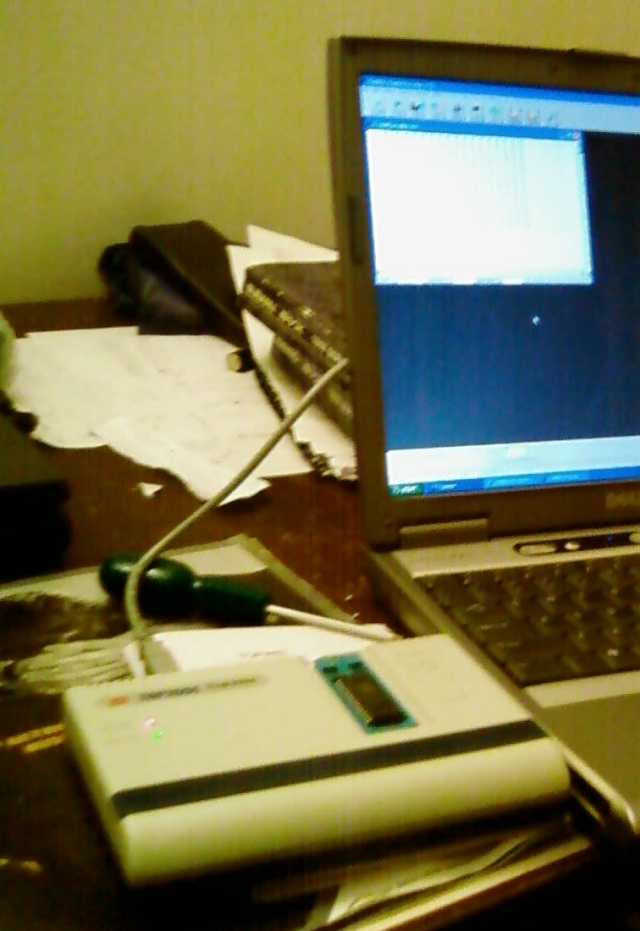
Program your modified ROM image into the two 27SF512 EEPROMS. I use a Top2004 programmer that I bought cheaply on ebay and it works very well. The size of the ROM image is 32K while the EEPROM chips are 64K each. You need to program the 32K image into the top half of each chip, starting at address 0x8000. I always append the image to itself to create a 64K image and then load that into the chipstarting from address 0x0000.
Step 5 - Install the upgrade in the ECU.
Install the EEPROMS in the ZIF sockets on the upgrade board. Then install the upgrade board in the upgrade socket of the ECU. Before attempting to start the engine, use the select monitor adapter to read back your ROM and verify that it is as expected.